The heart of a relay is an electromagnet (a coil of wire that becomes a temporary magnet when electricity flows through it). You can think of a relay as a kind of electric lever: switch it on with a tiny current and it switches on ("leverages") another appliance using a much bigger current.
Why is it useful?
Many sensors which we use in our daily life's and projects are sensitive to small currents and they require small amount of current for working. But we need to drive bigger loads or appliances using these sensors, so we have to use relays to bridge the gap, making it possible to activate or deactivate the bigger loads using small currents.Since relays are switches, the terminology applied to switches can also be applied to relays; a relay switches one or more poles, each of whose contacts can be thrown by energizing the coil.
 |
| Double Pole Double Throw Relay |
- Common (CO) : Common Terminal of the Relay or we can say that this pole is the common terminal of the switch.
- Normally-Close(NC) : Normally Close terminal, if relay is inactive then Common and Normally-Connected poles are connected.
- Normally-Open(NO) :Normally Open terminal, if relay is active then Common and Normally-Open poles are connected.
Categories of Relays:
- Single Pole Single Throw Relay ( Common and Normally Open Terminals)
- Single Pole Double Throw Relay ( Pair of Common and Normally Open Terminals )
- Double Pole Single Throw Relay ( Common, Normally Close and Normally Open Terminals)
- Double Pole Double Throw Relay ( Pair Common, Normally Close and Normally Open Terminals)
 |
| Types of Relay |
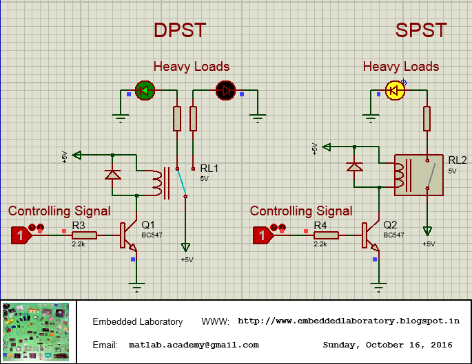
In Idle state, when relays are Off. Transistor is used to turn-on or off the relays, DPST relays has common, normally close and normally open terminals, so in idle state when relay is off, yellow led is glowing because 5V(Common) is directly connected to Yellow Led (Normally Close).
 |
| Relays are Off. |
 |
| Both Relays On. |
As you can see we have connected a diode in parallel with the relay coil, since the relay coil is an inductor, and it cannot change it's current instantly, the flyback diode provides a path for the current when the coil is switched off. Otherwise, a voltage spike will occur causing arcing on switch contacts or possibly destroying switching transistors.
Note:
The same circuit will work for most of the cases, as this circuit is fine when using DC loads, but when we have to deal with AC loads, this circuit will work, but it is not a good choice, as it can produce arcing, if switching doesn't take place at zero cross point. So for hobby based project, you can use this, but for commercial projects where AC loads switching is required, try to switch relays at zero cross point.


No comments:
Post a Comment