The Raspberry Pi is a credit-card-sized computer that plugs into your TV and a keyboard. It is a capable little computer which can be used in electronics projects, and for many of the things that your desktop PC does, like spreadsheets, word processing, browsing the internet, and playing games. It also plays high-definition video. It is being used by adults and children all over the world to learn programming and digital making.
In this post, we will see how we can use the Raspberry Pi to configure the GPIO's as output pin and use it to control the multiple Led's connected with the board.
There are lots of variant of Raspberry Pi available in the market, and in this tutorial, i am going to use the Model B having 512MB RAM and Rasbian Pixel OS installed on memory card.
 |
| Leds Connection with Raspberry PI |
Before proceeding further let's see how to connect the LED's with the Raspberry Pi (as shown in above figure) and for that we must know the pin out of the device. The pin out of Model B is as follow:
If you are using any other model of Raspberry PI, please use Raspberry PI Official website to view the pin out of your particular mode.
The Model B has 26 pins and LED's are connected with them as per the image given below.
Raspberry PI GPIO's are not capable of supplying and sinking large amount of currents (16mA), so we need to take care this factor while connecting LED's with Raspberry PI GPIO's. To solve this problem use a current limiting resistor between Raspberry Pi GPIO and Led so that the current consumption will be limited to less than 16mA.
Now after the connection is completed it's time to write the program for controlling LED's using Python, before proceeding further make sure that Raspberry Pi GPIO library is installed, although this library is installed by default but still it is better to update this library and this can be done by running the command "sudo apt-get install rpi-gpio", once the library is updated we can use the nano editor to write and run the Python program.
Lets discuss some of the important functions which we are going to use in our program.
The above program is self explanatory, but if still you don't understand it either watch the video given below or comment below in case of any problem.
Note: RPi.GPIO provides a built-in function GPIO.cleanup() to clean up all the ports you’ve used. But be very clear what this does. It only affects the ports you have set in the current program. It resets any ports you have used in this program back to input mode. This prevents damage from, the situation where you have a port set HIGH as an output and you accidentally connect it to GND (LOW), which would short-circuit the port and possibly fry it. Inputs can handle either 0V (LOW) or 3.3V (HIGH), so it’s safer to leave ports as inputs.
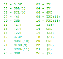 |
| Raspberry Pi Model B Pin Out |
The Model B has 26 pins and LED's are connected with them as per the image given below.
 |
| LED Connection |
Now after the connection is completed it's time to write the program for controlling LED's using Python, before proceeding further make sure that Raspberry Pi GPIO library is installed, although this library is installed by default but still it is better to update this library and this can be done by running the command "sudo apt-get install rpi-gpio", once the library is updated we can use the nano editor to write and run the Python program.
Lets discuss some of the important functions which we are going to use in our program.
- Setting Pin Mode
- GPIO.setmode(GPIO.BCM), this option means that you are referring to the pins by the "Broadcom SOC channel" number, these are the numbers after "GPIO"
- GPIO.setmode(GPIO.BOARD), this option specifies that you are referring to the pins by the number of the pin the the plug - i.e the numbers printed on the board (e.g. P1)
- Unfortunately the BCM numbers changed between versions of the Raspberry Pi, and you'll need to work out which one you have. So it may be safer to use the BOARD numbers if you are going to use more than one Raspberry Pi in a project.
- Setting Pin as Input or Output
- GPIO.setup(Pin_Number, OUTPUT) for configuring pin as Output Pin
- GPIO.setup(Pin_Number, INPUT) for configuring pin as Input Pin
- Turning Pin Configured as Output to High or Low States
- GPIO.output(Pin_Number, GPIO_HIGH) sets the pin to High State
- GPIO.output(Pin_Number, GPIO_LOW) sets the pin to Low State
- Reading Pin State configured as input
- GPIO.input(Pin_Number), this function returns High or Low depending on the Pin State.
So by using the above function, now we can write the program to turn on and off Led's one by one, the program is given below.
 import RPi.GPIO as GPIO
 import time
 led_array = [ 11, 12, 13, 15, 16, 18, 22, 7];
 blink_delay = 0.5
 try:
   GPIO.setmode(GPIO.BOARD)
   for i in range(0,8):
     GPIO.setup(led_array[i], GPIO.OUT)
     GPIO.output(led_array[i], False)
   # Infinite Loop
   while (True):
     for i in range(0, 8):
       GPIO.output(led_array[i], True)
       print led_array[i], 'pin On'
       time.sleep(blink_delay)
       GPIO.output(led_array[i], False)
       print led_array[i], 'pin Off'
       time.sleep(blink_delay)
 except KeyboardInterrupt:
   print "Exiting Program"
 except:
   print "Error Occurs, Exiting Program"
 finally:
   GPIO.cleanup()
The above program is self explanatory, but if still you don't understand it either watch the video given below or comment below in case of any problem.
Note: RPi.GPIO provides a built-in function GPIO.cleanup() to clean up all the ports you’ve used. But be very clear what this does. It only affects the ports you have set in the current program. It resets any ports you have used in this program back to input mode. This prevents damage from, the situation where you have a port set HIGH as an output and you accidentally connect it to GND (LOW), which would short-circuit the port and possibly fry it. Inputs can handle either 0V (LOW) or 3.3V (HIGH), so it’s safer to leave ports as inputs.


No comments:
Post a Comment